ezQuadcopter
ezQuadcopter Documentation
Table of Contents
- Introduction to Drones - How drones fly - How each componenent works - Propellers - Brushless Motors - Electronic Speed Controllers (ESCs) - Inertial Measurement Units (IMUs) - Gyroscope Sensor - Accelerometer - magnetometer - Radio-frequency Module - Flight Controllers - LiPo Batteries - Theoretical concepts - Control theory - Data fusion - Gimbal lock and quaternions - Security concerns
- Code Documentation
- Building a Quadcopter from A to Z
- Useful References
Introduction to Drones
How drones fly
How each component works
Propellers
Brushless Motors
Electronic Speed Controllers (ESCs)
Inertial Measurement Units (IMUs)
- Inertial measurement unit is an electronic sensor that measures the orientation of the object it is attached to.
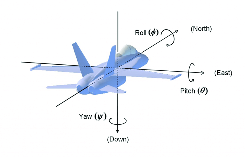
The orientation of an object is determined by essentially three values: Pitch, Roll and Yaw.
Here is a picture that you should never forget (because we’ll use these terms a lot!)
 we’ll discuss IMUs as in their use in flight controllers for drones.
 - IMUs usually use a combination of accelerometers, gyroscopes and magnetometers.
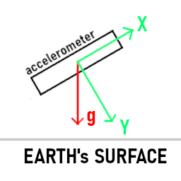
- Accelerometers can, to some extent, measure earth’s gravitational field at a particular point. (This is oversimplified of course, check this Wikipedia link for further details.)
- Gyroscopes measure the rate of rotation along the three axis. Gyroscopes are needed because accelerometer suffer from drift; essentially, accelerometers become less accurate overtime.
- Magnetometers can, to some extent, measure earth’s magnetic field. This is important to determine yaw rotation values.
We’ll dive deeper into each component in the sections below.
Accelerometer
Gyroscope Sensor
magnetometer
Radio-frequency Module
Flight Controllers
LiPo Batteries
Theoretical concepts
#### Control theory The feedback loop is at the heart of control theory. A feedback loop occurs when outputs of a system(or process) are transformed into inputs for the same system, thus forming a loop where the current output will be fed in as a form of input in the next iteration.
Maybe an example will make everything clear:
While you're driving your car in the highway, you decided to keep your speed constant at, let's say, 90 km\h.
You look to the speedometer you realize you're going 80 km\h, you realize that the difference between the current
speed and the desired speed isn't that high thus you slowly push the throttle. You keep looking at the speedometer,
you realize you're getting closer to the desired speed, it's 84 km\h, thus you slightly push the throttle. You keep
executing this loop during the whole journey until you reach your destination. Each time you measure
the output of your input (stepping on the throttle) by looking at the speedometer and you determine your _new_ input
from the measured speed value.
The goal of control theory is to develop a model that drives a system’s parameter(s) into a desired value.
Terminology
- Set Point : is the desired value for the parameter(s) the system controls
- Process Variable: is the measured value for the parameter(s) the system controls
- Error: is the difference between a set point and a measured process variable
In our previous anology:
- Set Point : speed of the car = 90 km\h
- Process Variable: That is the speed of the car measured through the speedometer
- Error: That is the difference between 90 km\h and the speed on the speedometer
Okay, but what does this have to do with drones?
-
Drones aren’t stable, even if you apply the exact same throttle to all the motors, chances it will crash immediatly. No, this has nothing to do with your piloting skills, it is due to the fact that it is impossible to build a perfect drone where the center of gravity is perfectly placed, where the motors rotate at the exact same speed, where the propellers are perfectly made, where …
-
And even if that was the case, what if a burst of wind destabilizes your drone while you’re not paying attention?
That is why we need control theory to guide the drone into the desired values.
What are those desired values?
- For a simple drone, those are the orientation values that the drone must target.
These values are:
- Pitch
- Roll
- Yaw
- These are either provided by the user through the remote-controller, or are set to a default
value when the drones receives no input from the user.
For instance, when the drone is IDLE (no input from the user), we want it to stabilize around these values:
- 0 for Pitch
- 0 for Roll
- 0 for Yaw
- For more complex drones, added to the orientation values, one might add:
- Speed
- Altitude
- Position
- etc…
- All of these parameters are measured by sensors. Some parameters could be even ‘measured’ by a camera.
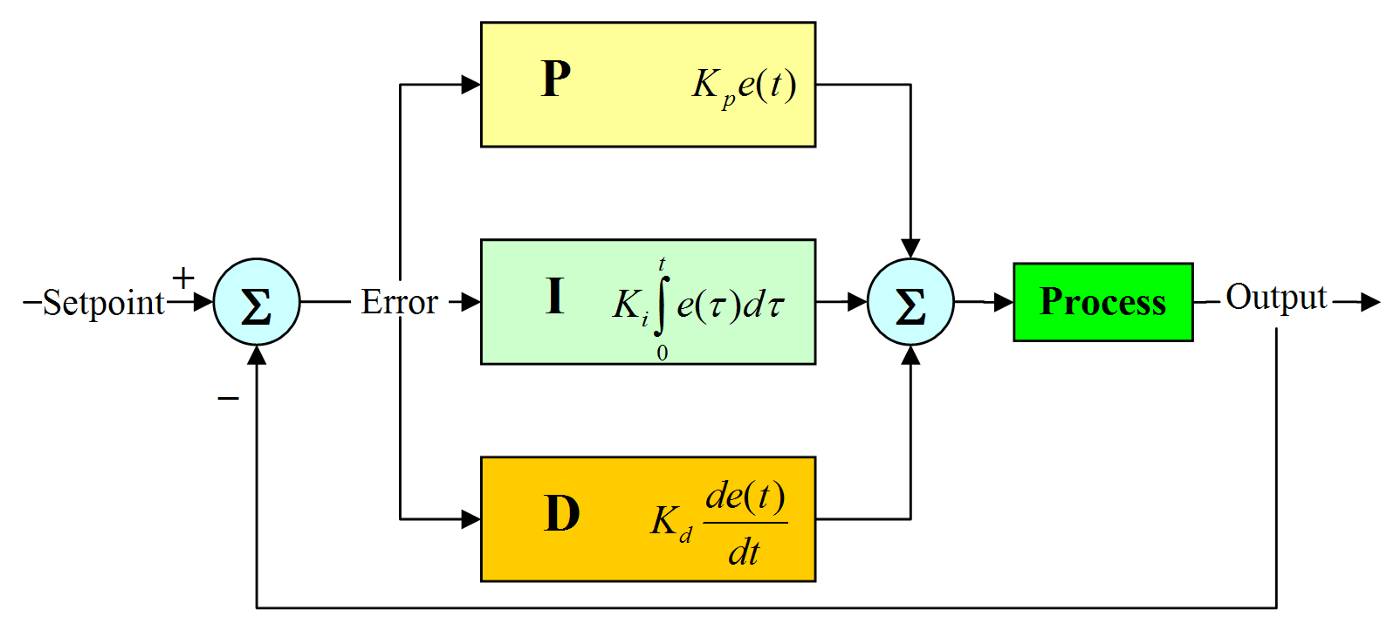
PID CONTROLLER
- Proportional–Integral–Derivative controller is a simple feedback loop mechanism that contineously calculates the Error and applies a correction based on proportional, integral and derivative terms of the error.
- It should be noted that PI and PD are also widely used controllers.
Okay… Maybe an example would be helpful?
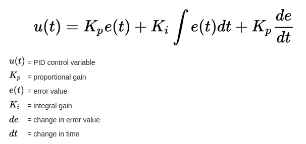
- Proportional correction: Applies an output(in other terms correction) proportional to the error
Let's go back to the car example, each time you measure the error, that is the difference between the set point (90 km\h) and
the speed measured from the speedometer, you apply a proportional force to the throttle pedal. For instance, you notice that
the error is 20 km\h thus you push somewhat hardly on the pedal. You notice the error is 4 km\h thus you slightly push the pedal.
- Derivative correction: Applies an output proportional to the rate of change of the error
The derivative term is used to avoid overshooting the set point.
In the same example, you realize the error is 30 km\h, that is a significant error thus you apply a proportional correction by flooring the peddal! After some time, the error is 25 km\h but you realize that you are rapidly approaching 90 km\h and that there is a risk that you will surpass that value (overshoot) that you decide to reduce the force by which you step on the pedal. - Integral correction: Applies an output proportional to the accumulated error You can think of the intergral term as an offset that compensates for a steady-state error that is present in your system.
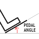
Up to this point, we assumed that the output of the PID controller is the change in force applied to the pedal thus when we reach
the desired speed,the output would be zero (that is no change in force applied to the peddal). But what if we want the output
to be an angle (see picture). In this case, even if you've reached the desired speed, the output of the PID shouldn't be
zero! Without the integral part, the output would be zero, that is a 0 angle which is wrong.
- Now, hopefully, you’ve got an indea about control theory and PID controllers in particular. You can check